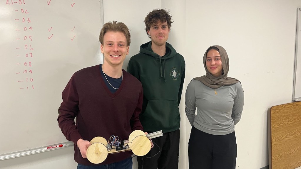
the goal of this project was to design and prototype a motor-driven platform that can move a 1-foot vertical bar back and forth without tipping it over. the challenge was speed vs stability. move as fast as possible, but never lose balance.
first part of the project was individually calculate the numbers, and simulate it using solid works. afterwards, the prototype was built as a group.
first, i calculated by hand the maximum horizontal acceleration the bar could tolerate without toppling. modeling it as a rigid body supported at its base, i found a theoretical limit of 0.817 m/s². this became the benchmark for everything that followed.
figure 1, moment equation
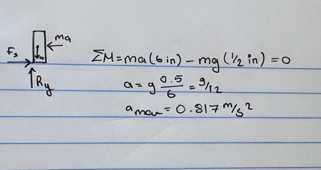
figure 2, solidworks eq
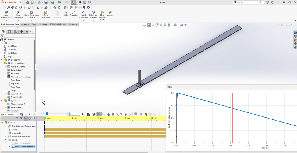
then i built a simplified solidworks model of the platform and bar to validate that number. by applying horizontal acceleration and tracking when the reaction force at the edge of the base dropped to zero, i confirmed the same tipping threshold. the simulation matched the hand calculations, which gave confidence that the model captured the core dynamics.
after that, i added wheels and a rotary motor to simulate realistic motion. we tested different wheel sizes and settled on 4.5-inch wheels. using a triangular velocity profile and the maximum allowable acceleration, the simulated car completed a 10-foot forward-and-back test in 7.72 seconds.
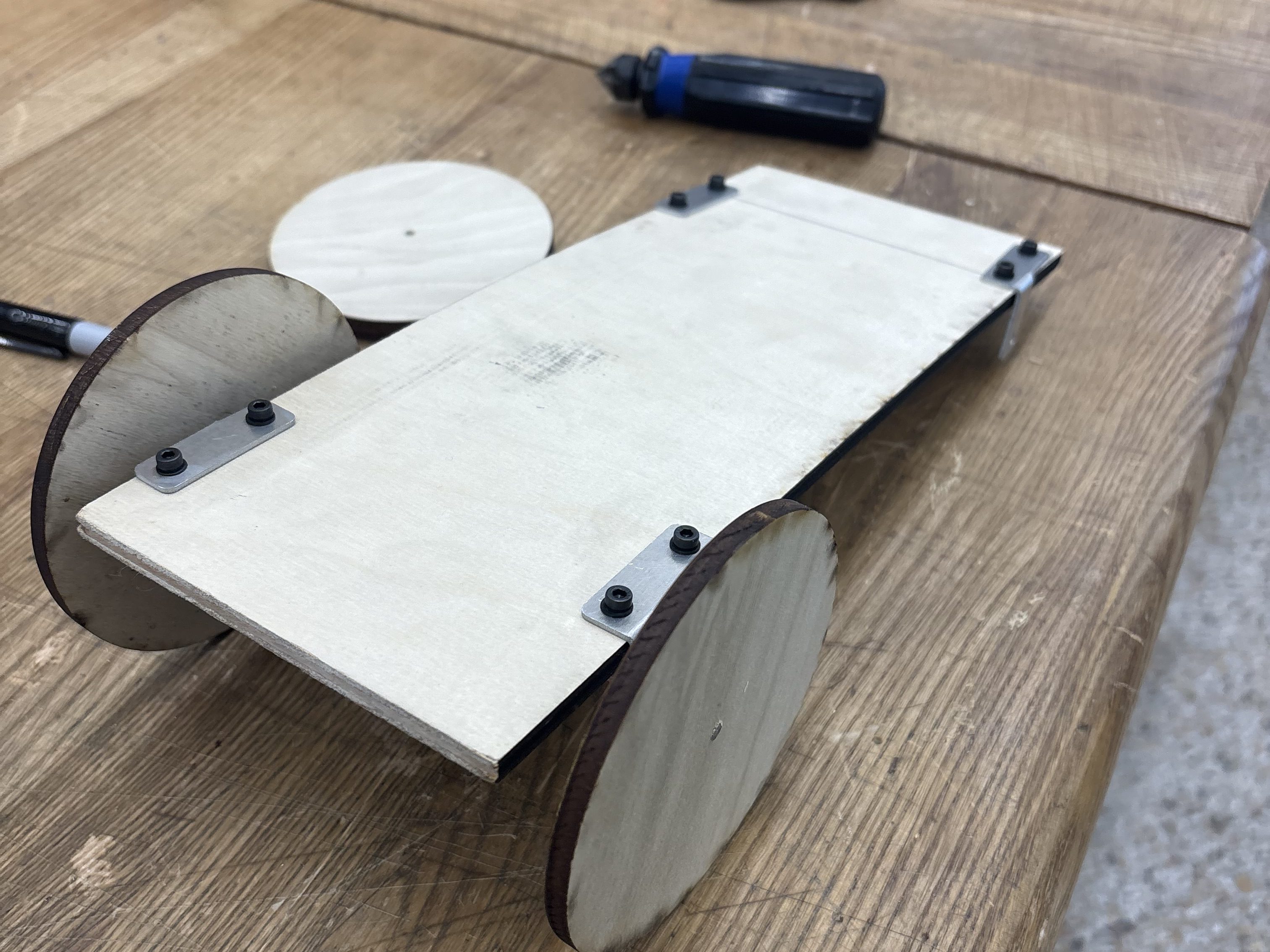
afterwards, we wired the motor to an arduino and wrote code to generate the same velocity profile. we assembled the chassis, mounted the wheels, and integrated the control system. in real testing, the true maximum acceleration dropped to around 0.4–0.5 m/s². air drag, vibration, surface imperfections, and other real-world effects reduced performance compared to the ideal model. this forced us to adjust the control strategy.
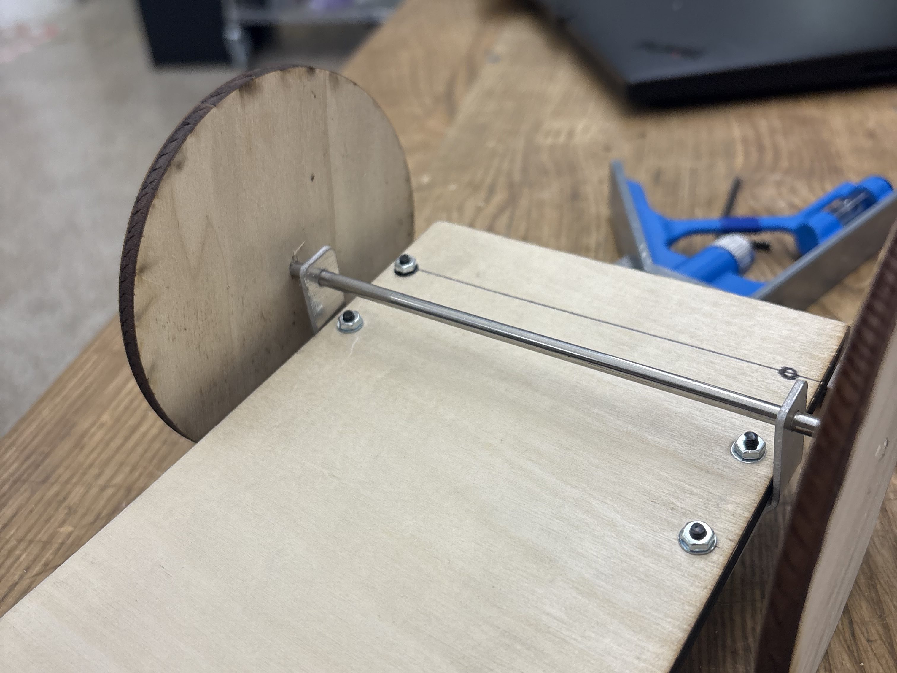
the first step of the physical build was designing the axle holders in solidworks and exporting the sketches as dxf files.
i took those files to epic and used the waterjet to cut them out of a thin aluminum sheet. after cutting, i used the sheet metal bending machine to form them into the final L shape. finally, i used a vertical drill press to enlarge the guide holes to the exact diameter needed for the axle, making sure the fit was precise and aligned.
in final class tests, the platform completed the 10-foot run in 11.2 seconds and the 6-foot run in 8.8 seconds. one key insight was that placing the bar diagonally increased its effective base width and improved stability. overall, the project showed the gap between simulation and reality and the importance of iterating between theory, cad, control, and physical testing.
void setup() { pinMode(2, INPUT); pinMode(3, INPUT); pinMode(5, OUTPUT); pinMode(6, OUTPUT); attachInterrupt(digitalPinToInterrupt(2), myFunction, RISING); Serial.begin(9600); } volatile long int count=0; int v_out=0; float currentSpeed=0; float error=0, kp=0.1, dv=0; float t=0; int target=0; unsigned long int t0=millis(); void loop() { float ramp = 2.2; // secondsfloat slope = 70; // RPM/s, same accelerationfloat rpmMax = slope*ramp; // 208 RPMt = float(millis() - t0)/1000;if (t < ramp) target = int(slope * t); // else if (t < 2*ramp) target = int(-slope*t + 2*rpmMax); // else if (t < 3*ramp) target = int(-slope*t + 2*rpmMax); // else if (t < 4*ramp) target = int(slope*t - 4*rpmMax); // else target = 0; //Serial.println(count); //Serial.println(target); delay(50); currentSpeed = getSpeed(50); //Serial.println(currentSpeed); Serial.println(error); error = target - currentSpeed; dv = kp*error; v_out = v_out + int(dv);if (v_out > 0) { analogWrite(6, v_out); digitalWrite(5, LOW); }else if (v_out < 0) { analogWrite(5, -v_out); digitalWrite(6, LOW); }else { digitalWrite(5, LOW); digitalWrite(6, LOW); } } void myFunction() { if (digitalRead(3) == HIGH) count++; else count--; } double getSpeed(int milliseconds) { float theta0 = 0.0, theta1 = 0 , w = 0; theta0=count; delay(milliseconds); theta1=count; w = (theta1-theta0) / float(milliseconds); return(w*90000.0/360.0); }the code generates a velocity profile based on a defined ramp time and acceleration. it calculates the target motor speed over time and uses a simple proportional controller to track that profile. by changing the ramp duration and acceleration values, we can reshape the motion without rewriting the control logic.