Engineering project / 2025
Autonomous Line-Following Vehicle
A differential-drive vehicle that reads a black path with five infrared sensors and corrects its motion in real time.
Developed for BU ENG EK210, the project combined a custom acrylic chassis, two geared DC motors, an Arduino-based sensing circuit, and PID steering logic. Our team designed the vehicle around a simple goal: follow a predefined path autonomously while leaving room for payload and obstacle-response requirements.
- Course
- BU ENG EK210
- Period
- 2025
- Team
- Yusuf Tasyurt, Derin Aysan, James Chang, and Neal Choksi
- Areas
- System testing, PID tuning, sensor integration, and assembly
- Tools
- Arduino/C++, infrared sensing, PWM motor control, and SolidWorks
Chassis design
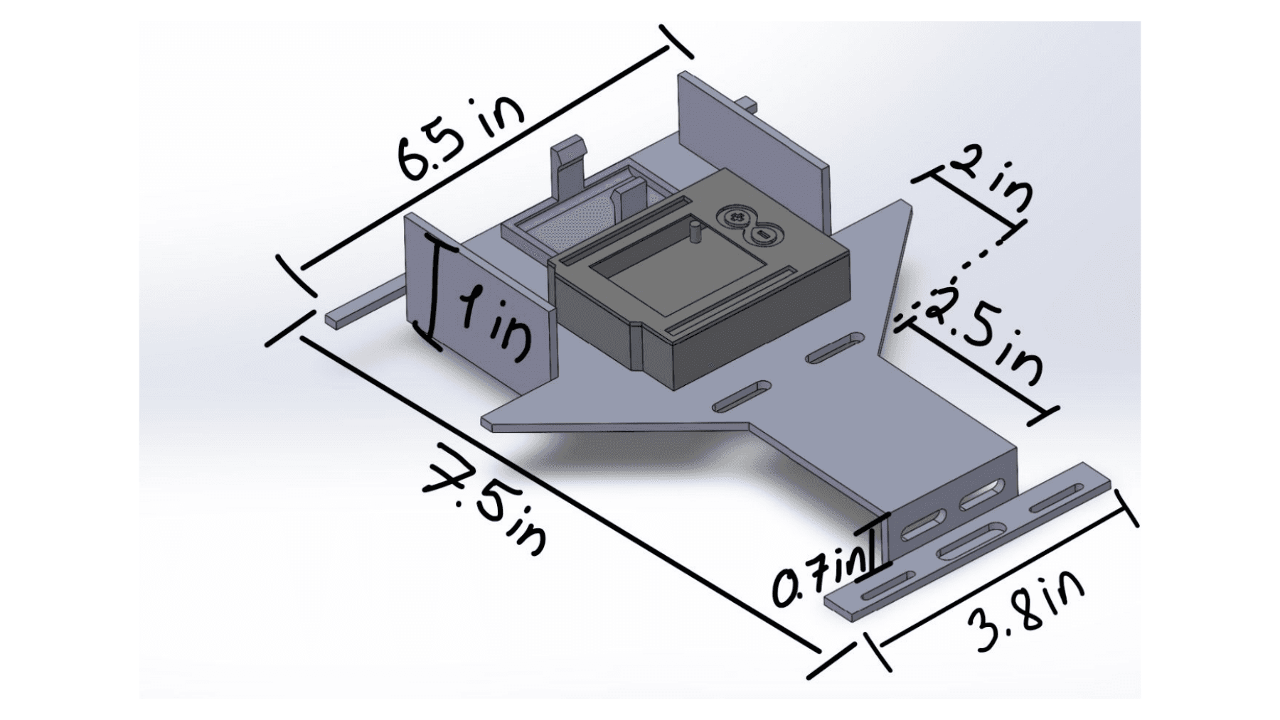
The team used SolidWorks to plan the chassis and component layout before assembly. The compact acrylic structure provided dedicated space for the Arduino and battery holders, routing cutouts for wiring, side mounting surfaces for the motors, and a front rail for the sensor array. The acrylic panels and electronics housings were bonded in place, while the caster was mechanically fastened.
Design brief
The vehicle needed to distinguish a black line from the surrounding surface and steer without manual input. The wider context was autonomous delivery, robotics, and manufacturing, where a machine can navigate a repeatable route using a simple physical guide.
We translated that problem into measurable targets. These were design objectives recorded by the team, rather than a claim that every target was fully validated in the presented prototype.
- Path
- Follow a black line continuously
- Payload
- Carry 250 g
- Response
- Stop or resume within 3 seconds
- Run time
- Operate for 1 hour
- Interaction
- Require only power on or off
Turning sensor readings into steering
The five-channel array reads the line at positions from far left to far right. The software assigns those channels weights of -2, -1, 0, 1, and 2, combining the active readings into a signed position error. A centered line produces little or no correction; a line offset to either side produces a correction in the opposite direction.
The PID calculation combines the current error, accumulated error, and change in error. Its output increases one wheel's PWM command while reducing the other, creating the speed difference needed to return the line toward the center of the sensor array.
- 01
Sense
Read five digital IR channels
- 02
Locate
Weight them -2, -1, 0, 1, 2
- 03
Correct
Calculate the PID response
- 04
Drive
Offset left and right PWM
- 05
Repeat
Measure the new line position
Electrical architecture
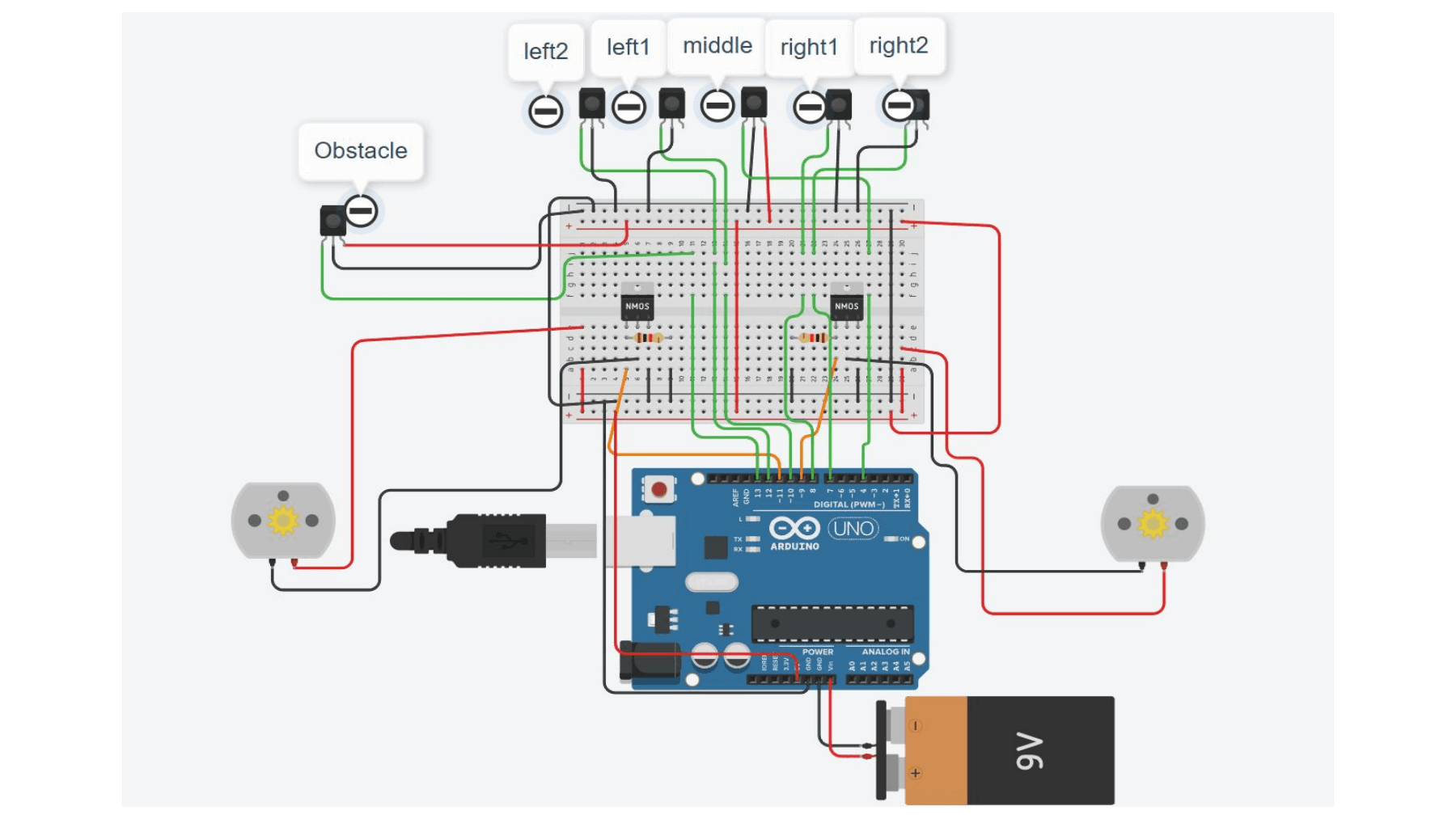
The Arduino receives five digital line-sensor signals and sends PWM commands through two nMOS switching stages to the left and right motors. The array operates from the Arduino's 5 V supply and was intended to sit roughly 0.5 to 3 mm above the track.
The motor study used a base command of 100 out of 255. With a 9 V switched supply, that corresponds to an approximate average of 3.5 V across a motor before accounting for switching and load effects.
Hardware and bill of materials
Control
Arduino Uno
Quantity: 1
Reads the sensors and executes the steering logic
Line sensing
Five-channel IR sensor array
Quantity: 1
Locates the black line across five digital inputs
Obstacle sensing
IR proximity sensor
Quantity: 1
Provides the planned braking input
Drive
TT 3-6 V DC gearmotor
Quantity: 2
Creates differential left- and right-wheel motion
Drive
Wheels and front caster
Quantity: 2 + 1
Supports and steers the three-point chassis
Motor switching
nMOS transistors and resistors
Quantity: 2 channels
Switches motor power from Arduino PWM commands
Power
9 V batteries
Quantity: Multiple
Supplies the controller and prototype drive system
Structure
Acrylic chassis and housings
Quantity: 1 set
Carries the electronics, batteries, sensors, and drive hardware
TT motor reference
Specifications documented during component selection.
- Rated voltage
- 3-6 V
- No-load current
- 150 mA +/- 10%
- Minimum speed at 3 V
- 90 RPM +/- 10%
- Minimum speed at 6 V
- 200 RPM +/- 10%
- Body dimensions
- 70 x 22 x 18 mm
- Motor mass
- 30.6 g
Prototype status and next iteration
The project established the vehicle's mechanical layout, sensing architecture, motor-control circuit, and PID correction strategy. Integrating the physical system made the relationship between sensor placement, chassis geometry, wiring, and software behavior visible as one coupled design problem.
The team's presentation identified the remaining work explicitly: tune the PID gains, integrate and test obstacle braking, stop when the line is lost for two seconds or when the vehicle crosses a terminal line, and replace the acrylic structure with a refined 3D-printed chassis.