Engineering project / 2026
Motor-Driven Transport Platform
How fast can a platform move a tall, unstable payload without tipping it over?
The project began with rigid-body dynamics, moved into SolidWorks motion studies, and ended as a fabricated Arduino-controlled vehicle. The central tradeoff stayed the same throughout: increase speed while keeping a 1-foot vertical bar stable during forward and reverse travel.
- Type
- Team design project
- Period
- 2026
- Challenge
- Move a 1-foot vertical bar without toppling it
- Areas
- Dynamics, motion simulation, fabrication, controls, and testing
- Tools
- SolidWorks Motion, Arduino/C++, waterjet, sheet-metal brake, and drill press
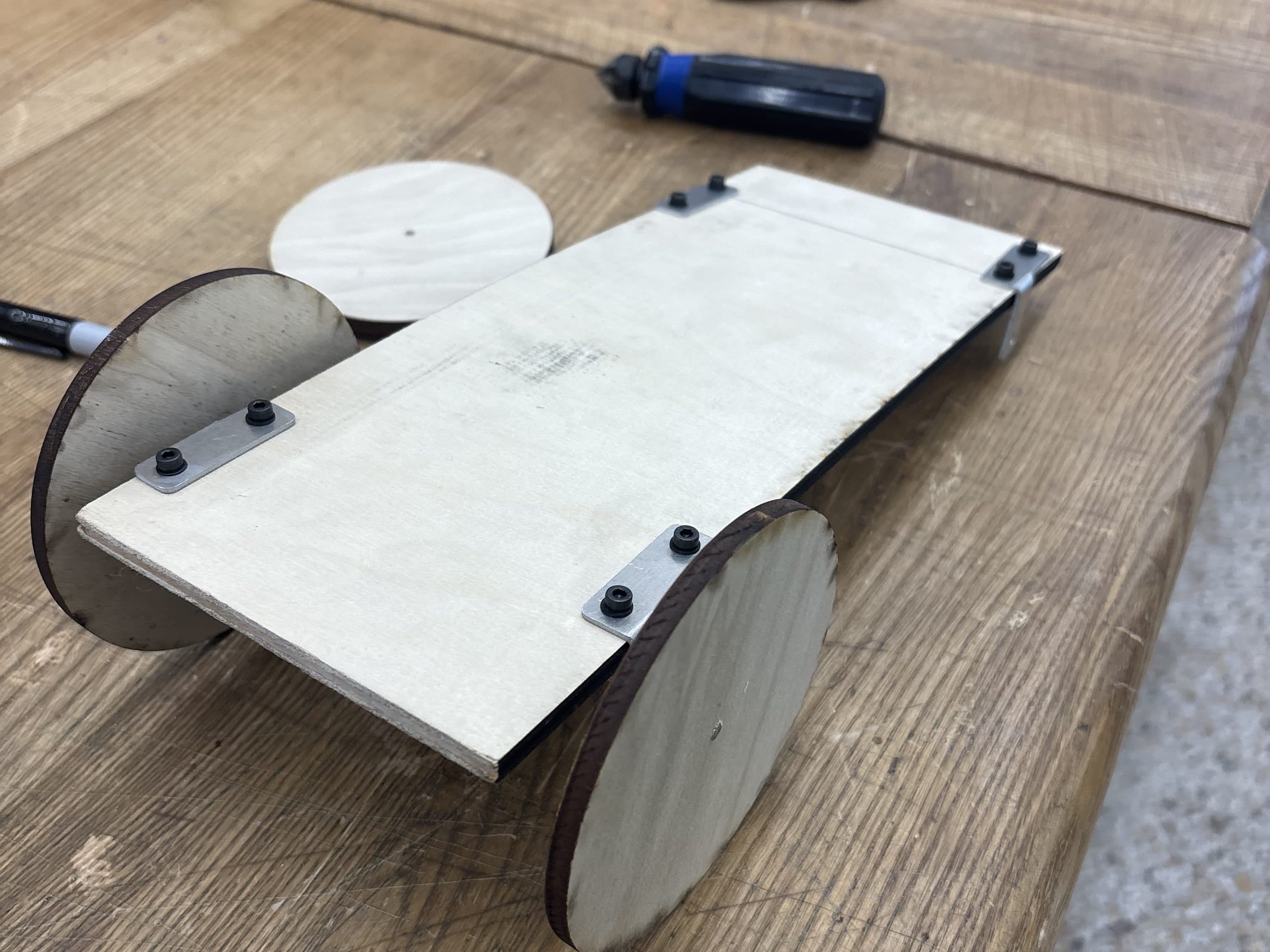
Working platform
Defining the stability limit
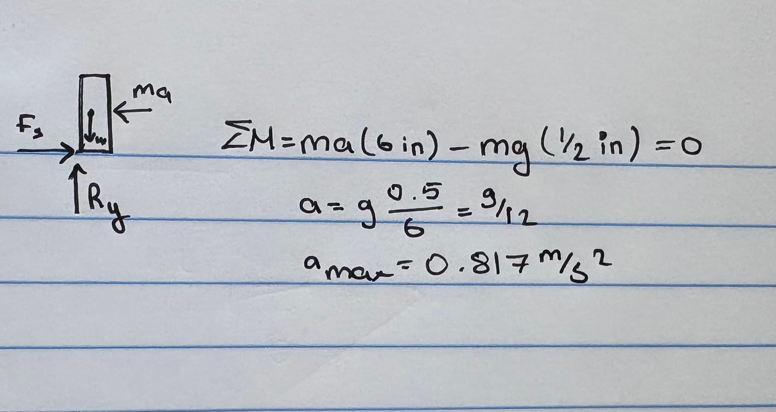
The initial analysis treated the bar as a rigid body supported at its base. At the tipping threshold, the moment created by horizontal acceleration balances the restoring moment from gravity. Using the bar's 6-inch center-of-mass height and 0.5-inch half-width, the calculation produced a theoretical maximum horizontal acceleration of 0.817 m/s².
That value became the first design constraint. It was high enough to make the platform move quickly, but low enough to keep the predicted contact force inside the bar's narrow base.
Validating the model in SolidWorks
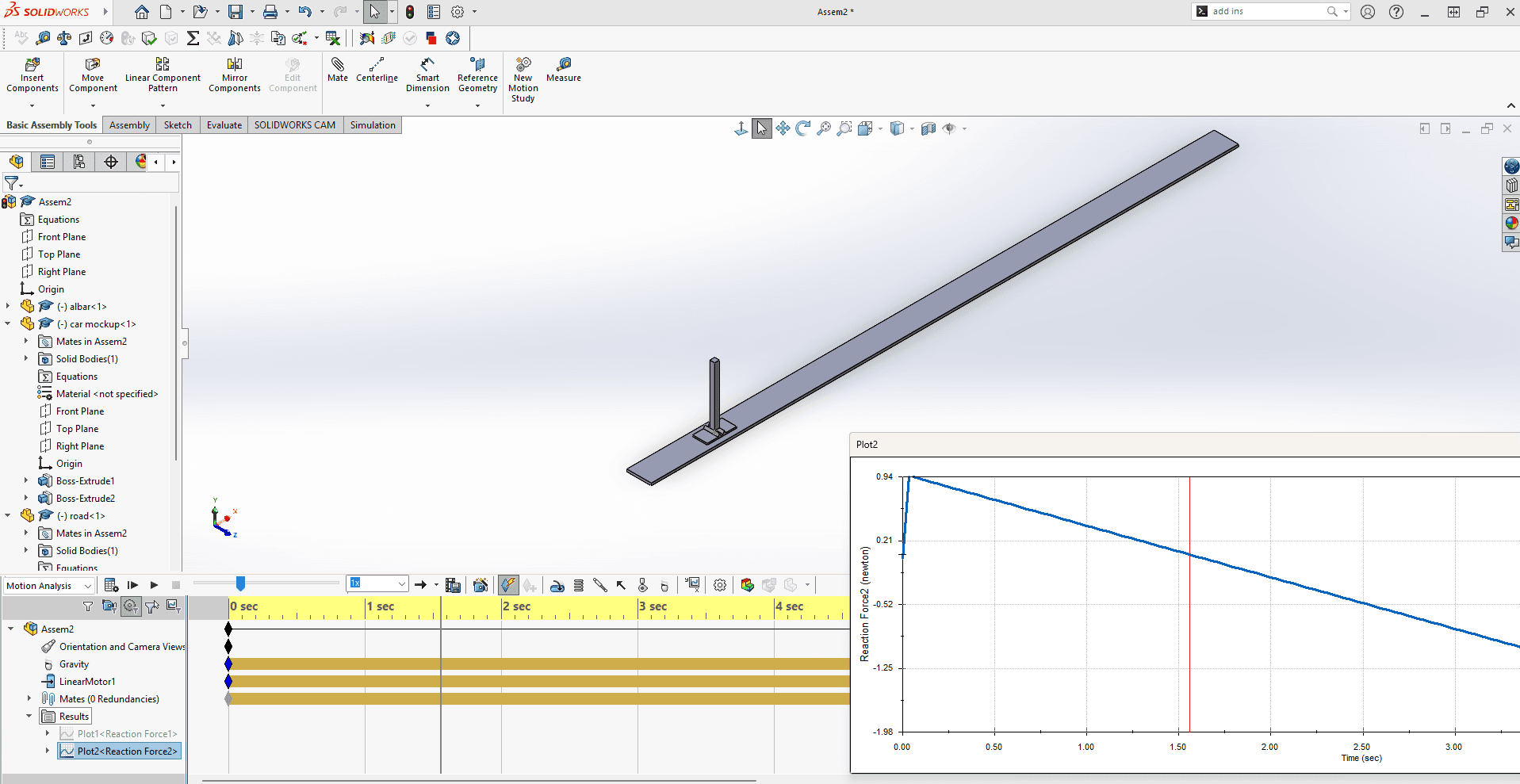
The initial SolidWorks study recreated the platform and bar as a simplified assembly, applied horizontal acceleration, and tracked the reaction force at the edge of the base. The reaction reached zero at the same tipping threshold predicted by the hand calculation, giving the team confidence that the model captured the essential dynamics.
Starting from that validated model, I added wheels and a rotary motor, compared wheel sizes, and selected 4.5-inch wheels. With a triangular velocity profile based on the theoretical acceleration limit, the simulated platform completed a 10-foot forward-and-back cycle in 7.72 seconds.
Fabrication and assembly
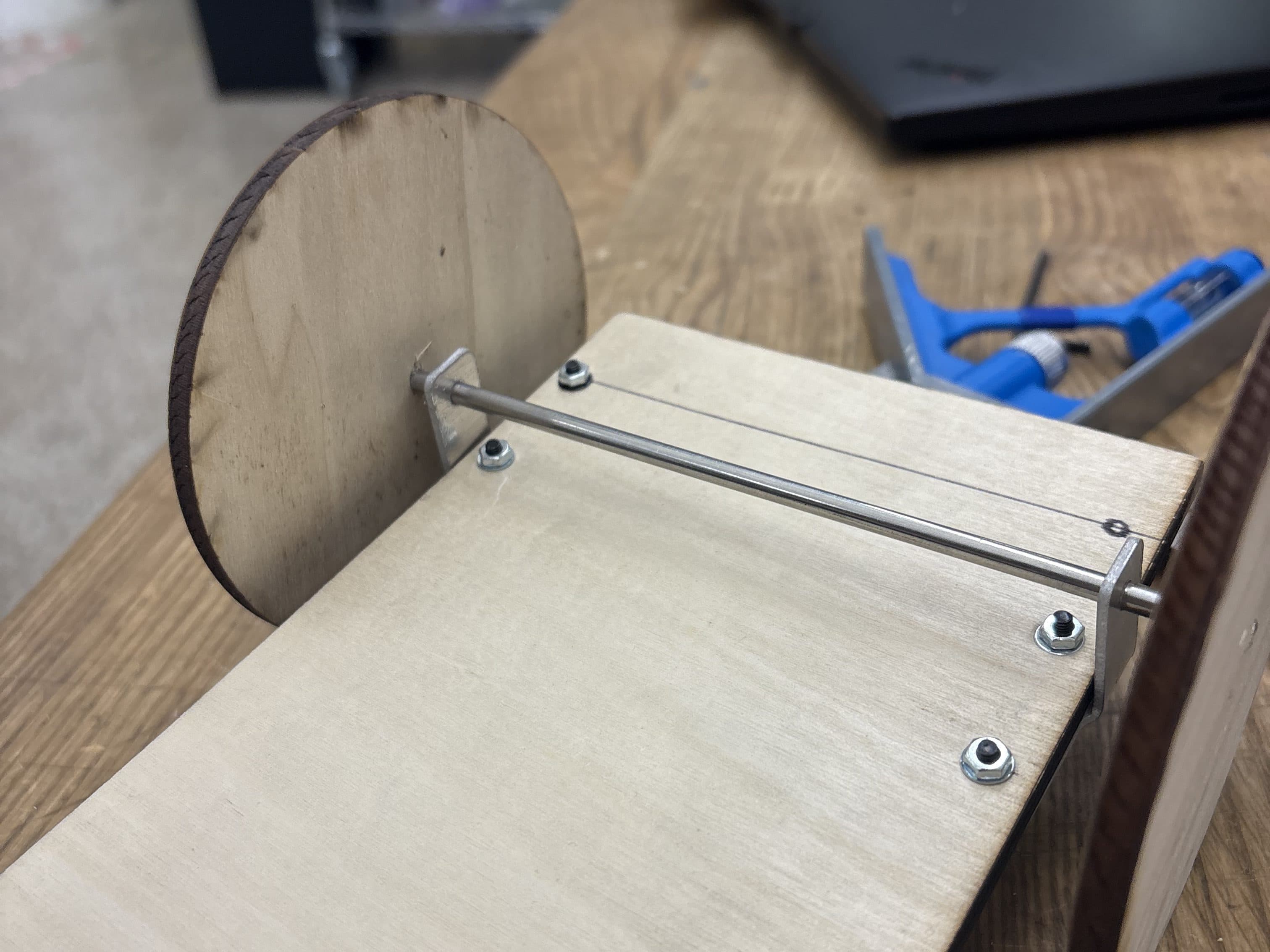
I designed the axle holders in SolidWorks and exported their sketches as DXF files. I cut the parts from thin aluminum sheet on the EPIC waterjet, formed them into L-shaped brackets with the sheet-metal brake, and enlarged the guide holes on a vertical drill press to achieve the required axle fit and alignment.
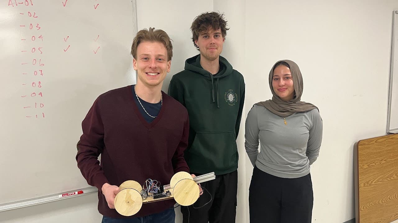
The team assembled the plywood chassis, mounted the 4.5-inch wheels, installed the axle and brackets, and integrated the motor, encoder, Arduino, and power electronics into a single testable platform.
Motion control
The Arduino generated the same triangular velocity pattern used in simulation. An encoder interrupt measured wheel rotation, while a proportional controller compared measured speed with the current target and updated the motor command.
Ramp duration and slope remained parameters, so the team could reduce acceleration after physical tests exposed vibration, drag, and surface effects that were absent from the ideal model.
Feedback
Encoder pulse count sampled over 50 ms
Controller
Proportional speed correction
Output
Bidirectional PWM motor command
Simulation and test results
Acceleration limit
- Model or simulation
- 0.817 m/s²
- Physical test
- Approximately 0.4-0.5 m/s²
10-foot forward-and-back run
- Model or simulation
- 7.72 s
- Physical test
- 11.2 s
6-foot forward-and-back run
- Model or simulation
- Not recorded
- Physical test
- 8.8 s
Outcome and reflection
Physical testing reduced the usable acceleration to roughly 0.4-0.5 m/s². Air drag, vibration, surface imperfections, and compliance pushed the real system away from the idealized model, so the team reshaped the motion profile rather than forcing the original limit onto the hardware.
The final platform completed the 10-foot forward-and-back run in 11.2 seconds and the 6-foot run in 8.8 seconds. Placing the bar diagonally increased its effective support width and improved stability. The project made the gap between calculation and hardware tangible: the useful design emerged by moving back and forth between theory, CAD, controls, fabrication, and testing.