
Engineering project / 2024
Room Temperature Monitoring Device
An Arduino temperature monitor with a two-line display and visual and audible safe-range alerts.
Developed for EK 130, the device reads a TMP36 sensor, displays room temperature in Celsius and Fahrenheit, and warns the user when the reading falls outside a programmed range. The project combined firmware, circuit assembly, enclosure layout, and final integration in a portable ABS housing.
- Course
- BU EK 130
- Period
- 2024
- Format
- Individual design and build project
- Areas
- Embedded systems, circuit assembly, CAD layout, and prototyping
- Tools
- Arduino/C++, CAD, soldering, and 3D printing
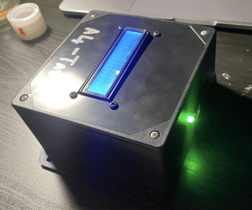
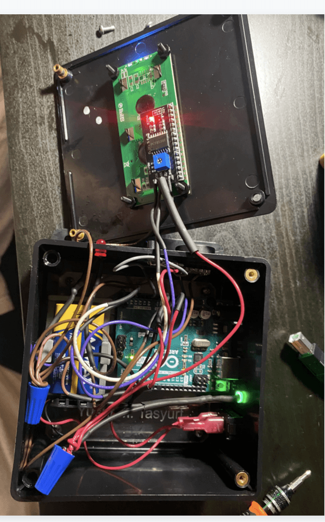
Finished device
System operation
The TMP36 produces an analog voltage proportional to temperature. The Arduino samples that signal on A0, converts the ADC reading to voltage, and uses the sensor's 500 mV offset and 10 mV/°C scale to calculate temperature. Celsius and Fahrenheit values are refreshed on the LCD every 500 milliseconds.
The programmed safe range is 80-85 °F. Outside that interval, the controller flashes the red LED and pulses the buzzer four times. The green LED remains on as a separate power-status indicator, and the firmware performs a short red-LED and buzzer check at startup.
- 01
Read
Sample the TMP36 on analog input A0
- 02
Convert
Convert ADC value to voltage, then Celsius and Fahrenheit
- 03
Display
Update both temperature values on the 16x2 LCD
- 04
Compare
Check the Fahrenheit value against the 80-85 °F range
- 05
Alert
Flash the red LED and pulse the buzzer when outside the range
Enclosure and component layout
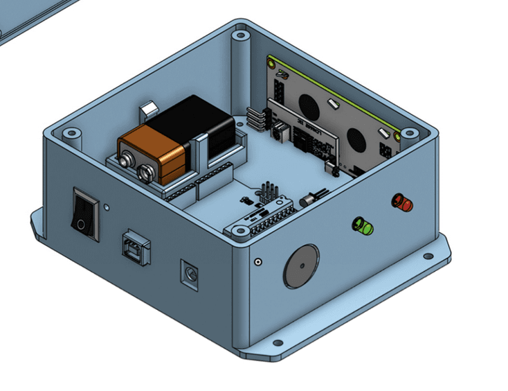
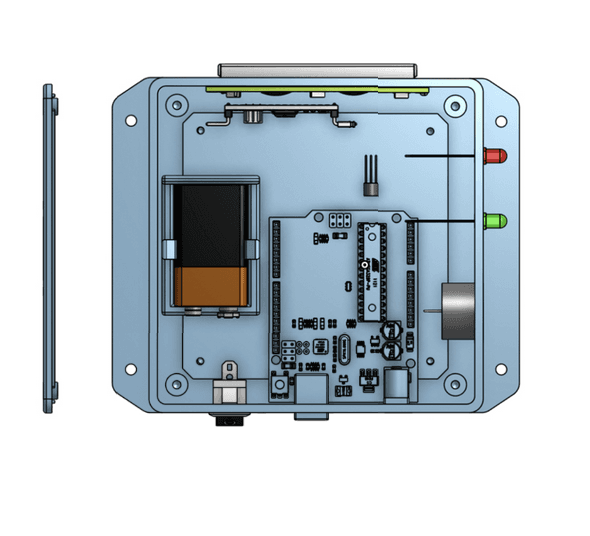
The enclosure model was used to place the LCD, Arduino, battery, switch, sensor, indicators, and buzzer before assembly. The LCD occupied the lid; the switch and green power indicator shared one side; and the TMP36, red alert LED, and buzzer were grouped on the adjacent side near the controller. The physical build followed the CAD layout without requiring a major rearrangement.
Circuit and assembly
The Arduino served as the central controller for the sensor, display, indicators, and buzzer. The LCD used an I2C connection, while the TMP36 supplied the analog input used by the firmware. The completed device could run from either the internal 9 V battery or USB power.
Circuit connections used 22 AWG wire, soldered joints, spade connectors at the switch, heat-shrink insulation, and wire connectors for shared nodes. A 220-ohm resistor limited current through the red alert LED, while a 1-kilohm resistor reduced the always-on green indicator's current and brightness.
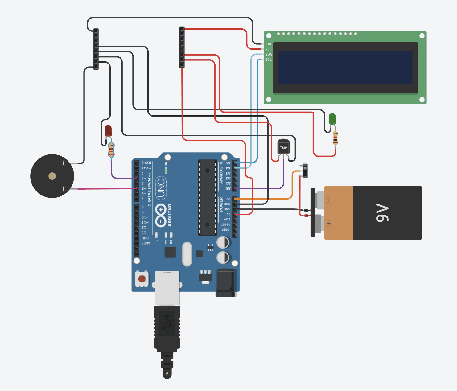
Component system
Sensing
TMP36 temperature sensor
Measures room temperature as an analog voltage
Control
Arduino Uno
Reads the sensor, converts units, updates the display, and controls alerts
Interface
16x2 I2C LCD
Displays temperature in Celsius and Fahrenheit
Alert
Buzzer and red LED
Activate when temperature leaves the programmed range
Status
Green LED
Indicates that the device is powered
Power
9 V battery or USB
Supports portable or externally powered operation
Housing
ABS enclosure and printed battery holder
Locates and protects the assembled electronics
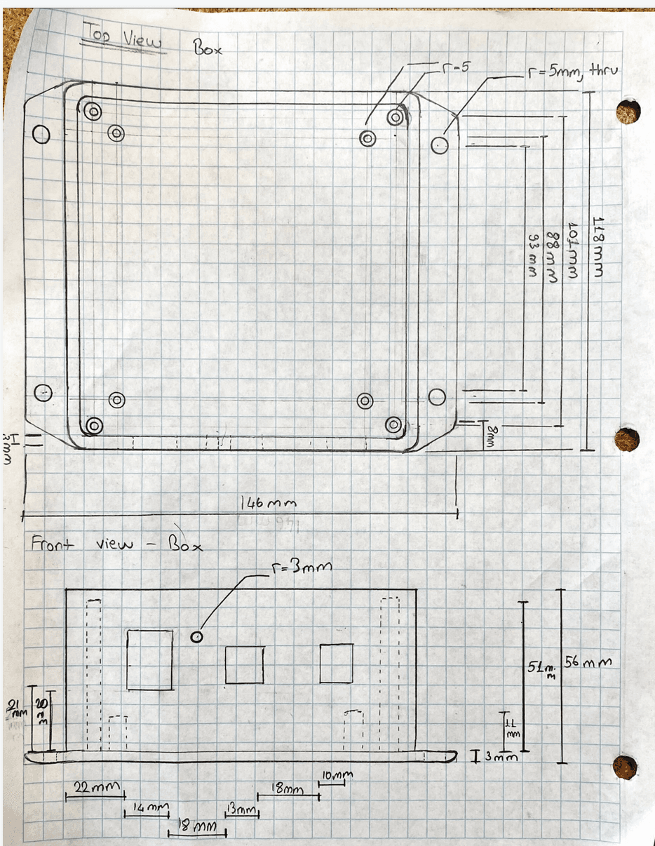
Mechanical documentation
Hand measurements established the enclosure geometry and the required openings before the components were placed in CAD. The main ABS housing measured approximately 117 x 118 x 59 mm. The drawings also recorded the LCD opening, lid fasteners, side-panel controls, and the clearances needed around the internal hardware.
Result and evaluation
The finished device read the TMP36, displayed both temperature units, and activated the red LED and buzzer outside the selected range. It operated from its internal battery and from USB, and the CAD layout translated successfully into the physical enclosure.
The prototype also exposed clear limitations. The Arduino Uno, full-size LCD, wiring, and battery produced a bulky package; battery life was limited; and the temperature signal was not filtered or characterized across the sensor's full range. A smaller controller and display, measured current consumption, averaged sensor readings, and a purpose-built circuit board would make a later version smaller and more reliable.